
3D Scanning for Quality Inspection & GD&T Verification: Advanced Metrology for Indian Manufacturing
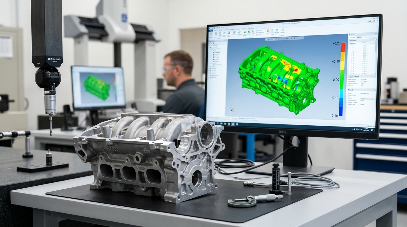
Quality inspection in modern manufacturing is no longer about measuring a few critical dimensions with a vernier caliper or even a Coordinate Measuring Machine (CMM). As component complexity increases — driven by tighter GD&T callouts, complex free-form surfaces, and compressed product development timelines — manufacturers across India's industrial corridors (Pune, Delhi NCR, Bengaluru, Chennai, and Faridabad) are rapidly adopting 3D scanning-based metrology as their primary quality inspection and process verification tool.
Unlike point-to-point CMM inspection, 3D scanning captures the complete surface of a component — hundreds of thousands to millions of data points — in minutes. This full-surface dataset enables color deviation maps, statistical process capability analysis, GD&T geometric tolerance verification, and first article inspection reports with a depth of insight that traditional measurement methods simply cannot provide. This guide explains the technology, workflow, and industrial applications of 3D scanning for quality inspection, with specific context for Indian manufacturing environments.
1. Limitations of Traditional CMM Inspection — Why 3D Scanning is Taking Over
Coordinate Measuring Machines (CMMs) have been the gold standard of industrial dimensional metrology for decades. However, as component geometries become more complex and inspection throughput requirements increase, CMMs reveal significant operational limitations:
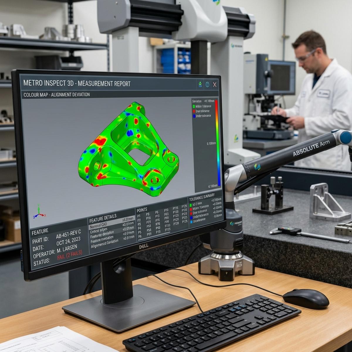
Full-surface color deviation map comparing scanned automotive injection-molded part against CAD nominal — showing warpage and sink mark deviations at ThinkToReality inspection lab, Greater Noida.
2. How 3D Scanning Quality Inspection Works: The Technical Workflow
3D scanning-based quality inspection follows a well-defined metrological workflow:
Step 1 — Reference CAD Import: The nominal CAD model (STEP or IGES file) of the part is imported into inspection software (GOM Inspect, PolyWorks Inspector, or Verisurf). This establishes the theoretical reference geometry against which the physical part scan will be compared.
Step 2 — Part Scanning: The physical component is 3D scanned using structured light or laser triangulation scanning to generate a dense point cloud or polygon mesh representing the part's as-manufactured geometry.
Step 3 — Best-Fit Alignment (Registration): The scan mesh is aligned to the CAD model using either: (a) Best-Fit Alignment — mathematically minimizes the overall deviation between scan and CAD across all surfaces; or (b) RPS (Reference Point System) Alignment — aligns via specific datum features (datum planes A, B, C per GD&T drawing callouts), reflecting how the part is functionally constrained in its assembly.
Step 4 — Full-Surface Deviation Analysis: Software computes the 3D distance between every scanned point and the nearest CAD surface. Results are displayed as a color deviation map — a visual heat map where colors represent deviation magnitude: typically blue/green for within tolerance, yellow for near-limit, and red for out-of-tolerance regions. This instantly reveals warpage, shrinkage, sink marks, machining errors, and form deviations across the entire component.
Step 5 — GD&T Feature Extraction & Verification: Geometric dimensioning and tolerancing features are extracted from the aligned scan: flatness, cylindricity, perpendicularity, true position, profile of a surface, angularity, runout, and concentricity. Each feature is measured against its drawing tolerance, and pass/fail results are automatically tabulated.
Step 6 — Inspection Report Generation: A comprehensive digital inspection report is generated with: color deviation maps, GD&T feature tables (nominal vs. actual vs. deviation vs. tolerance), statistical summaries (Cp, Cpk process capability), and annotated part views highlighting critical deviations — suitable for PPAP (Production Part Approval Process) submissions and customer review.
3. GD&T Verification with 3D Scanning: Feature-Level Analysis
GD&T (Geometric Dimensioning and Tolerancing) is the universal engineering language for communicating part form, fit, and function requirements. 3D scanning enables comprehensive GD&T verification beyond what manual or CMM inspection typically delivers:
4. First Article Inspection (FAI) & PPAP with 3D Scanning
First Article Inspection (FAI) is mandatory for new part releases in automotive (IATF 16949), aerospace (AS9100), and defense (DRDO) supply chains. Traditional FAI using CMM and manual measurement of a 100-feature injection-molded automotive component can take 2–4 days. 3D scanning FAI for the same component: 4–8 hours total, with higher feature coverage and automatic report generation.
PPAP (Production Part Approval Process) submissions to automotive OEMs (Maruti Suzuki, Tata Motors, Mahindra, Hyundai India) require dimensional inspection reports with full GD&T coverage. 3D scanning inspection reports meet PPAP Level 3 requirements with full-surface deviation maps, GD&T tables, and statistical capability data — in a professional, audit-ready digital format.
India's Tier-1 and Tier-2 automotive suppliers in Pune's Chakan corridor, Delhi NCR's Gurgaon-Manesar-Faridabad belt, and Chennai's Sriperumbudur zone are increasingly specifying 3D scanning FAI as a supplier qualification requirement.
5. Applications in Indian Manufacturing Sectors
6. 3D Scanning Quality Inspection Services — ThinkToReality, Greater Noida
ThinkToReality's 3D laser scanning inspection service provides industrial-grade metrology for manufacturers across Delhi NCR and beyond. Our digital inspection workflow delivers color deviation maps, GD&T feature tables, and PPAP-compatible inspection reports for automotive, aerospace, medical device, and industrial equipment manufacturers.
We regularly support quality inspection for clients in Noida, Greater Noida, Gurgaon, Faridabad, Delhi, Agra, Lucknow, and across the NCR manufacturing belt. Our portable scanning capability also allows on-site inspection at customer facilities for large assemblies and installed equipment that cannot be transported to our metrology lab.
Inspection services offered: First Article Inspection (FAI), Production batch sampling inspection, Incoming component verification, Tooling qualification, Assembly alignment verification, Process deviation root cause analysis, and reverse engineering baseline capture.
If your manufacturing operation faces quality escapes, supplier deviation disputes, or PPAP approval challenges — 3D scanning inspection delivers the definitive, defensible measurement data to resolve them quickly. Contact ThinkToReality for an inspection service consultation or submit your part drawing for a quote.
Need High-Precision 3D Printing?
Advanced SLA resin, SLS nylon, and FDM 3D printing services for fast, high-quality functional prototyping in Delhi NCR.
Related Engineering Insights
3D Laser Scanning for Reverse Engineering: Complete Guide to Industrial Part Digitization in India
A comprehensive technical guide to 3D laser scanning for reverse engineering of industrial components. Learn how structured light & laser triangulation scanners digitize metal parts to ±0.01mm accuracy, generate STL/STEP files, and enable precision redesign — with applications across automotive, aerospace, and defense manufacturing in Delhi NCR, Pune, and Bengaluru.
VMC Machining vs CNC Milling: Engineering Differences, Workholding & Precision Metal Works in India
A comprehensive engineering guide comparing Vertical Machining Centers (VMC) and traditional CNC milling for custom metal parts. Learn key mechanical differences, 3-axis/4-axis/5-axis spindle configurations, precision workholding, GD&T tolerances (±0.005mm), and industrial metal job work in Delhi NCR & across India.