
DFM for CNC Milling: 5 Common Design Mistakes That Double Your Machining Costs
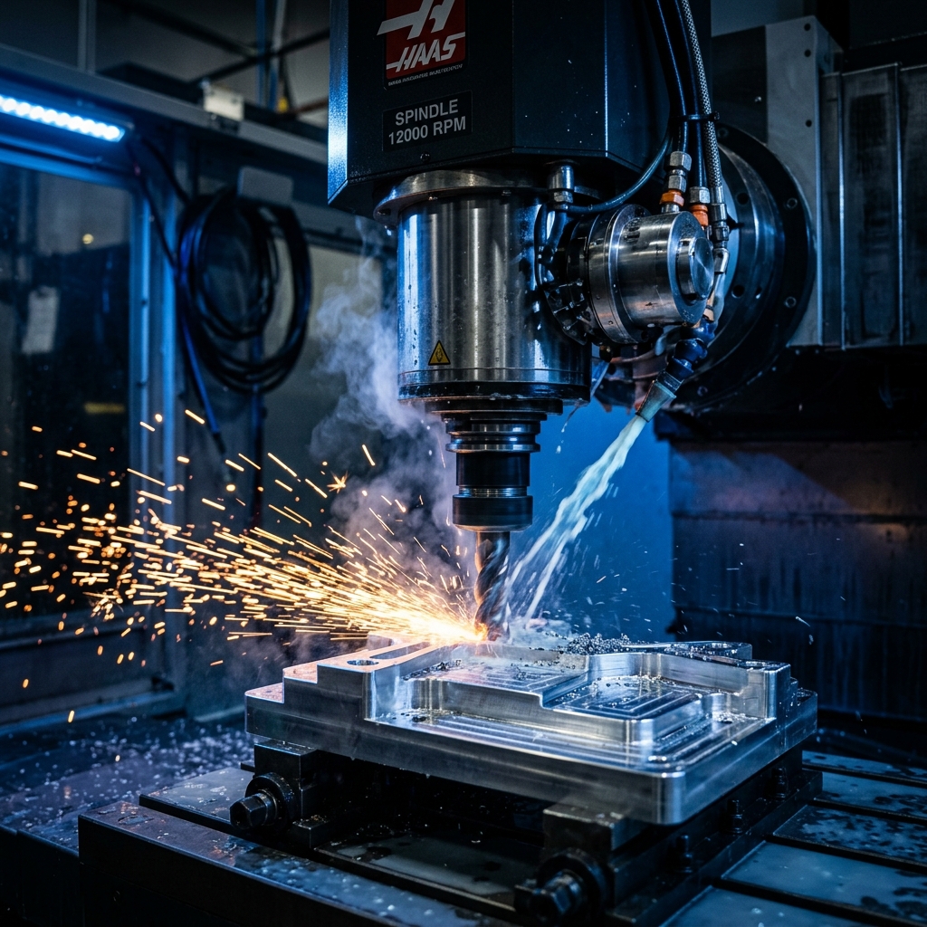
Design for Manufacturing (DFM) is an engineering practice that optimizes part geometries to reduce production time, minimize scrap, and lower machining costs. In CNC milling, where material is subtracted from a solid block using rotating cutting tools, nominal design features directly dictate the complexity of machining setups and machine runtime. At ThinkToReality, our engineering teams perform thorough DFM evaluations on every CAD upload to ensure that customer designs are fully optimized for manufacturing before machining begins.
Failing to account for the physical limitations of CNC cutters during the initial CAD design phase is a leading cause of project budget overruns. When features are drawn without considering tool reach, cutter diameters, or material rigidity, machinists are forced to use specialized tooling or perform multiple manual part repositionings. In this guide, we break down the 5 most common CNC design errors and how to fix them.
1. Sharp Internal Corners
Rotating milling tools like end mills are cylindrical. Consequently, they cannot machine a sharp 90-degree internal vertical corner. If a CAD design specifies a sharp internal corner, the machinist will be forced to use specialized EDM (Electrical Discharge Machining) which adds significant cost and cycle time. To optimize for CNC milling, designers should always add an internal radius to all vertical corners. Ideally, make the corner radius slightly larger (e.g., 10% larger) than the radius of the milling tool. This prevents the cutter from binding in the corner, reducing tool wear and chatter.
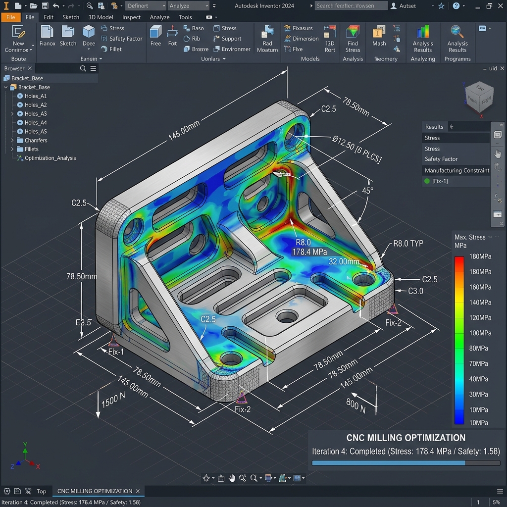
Precision CAD modeling showing the difference between sharp corners (unmachinable) and radiused corners (optimized for CNC).
2. Overly Deep and Narrow Pockets
Deep cavities require long end mills to reach the bottom. However, long-reach cutting tools are highly susceptible to deflection, vibration, and tap breakage. Tool deflection leads to dimensional inaccuracies and poor surface finishes, requiring slow feed rates to compensate. As a rule of thumb, pocket depth should not exceed 4 times the pocket width. Keeping pockets shallow allows standard-length cutters to be used at high speeds, reducing runtime.
3. Unreasonably Thin Walls
Thin walls lack structural stiffness. Under the physical forces of a rotating cutter, thin sections will flex and vibrate, leading to chatter marks and dimensional errors. In extreme cases, the wall can warp or fracture entirely. For plastic parts, maintain a minimum wall thickness of 1.5mm. For metal components like aluminum or steel, maintain a minimum of 0.8mm to ensure structural stability during heavy milling operations.
4. Overly Tight Tolerances
Demanding micron-level tolerances where standard tolerances (e.g., ±0.1mm) are perfectly fine is an expensive mistake. Tight tolerances require slower machining speeds, frequent tool inspections, specialized metrology equipment, and high scrap rates. Only apply tight tolerances to critical interface features like bearing seats or mating slides. Leave non-mating dimensions at standard machining tolerances.
5. Blind Tapped Holes That Are Too Deep
Designing threads that extend to the very bottom of a blind hole is highly problematic. Cutting threads requires tap clearance at the bottom of the hole. Furthermore, threads deeper than 3 times the hole diameter provide no additional holding strength; instead, they increase the risk of tap binding and breakage. Limit thread depths to 2 times the nominal thread diameter to ensure clean, easy tapping.
Conclusion: Streamlining Your Design Cycle
By implementing these basic DFM rules—adding internal corner radii, limiting pocket depths, maintaining wall thickness, relaxing non-critical tolerances, and limiting thread depths—you can easily reduce your CNC machining costs by up to 50%. Partnering with a digitally integrated manufacturing shop like ThinkToReality ensures your CAD designs are reviewed and optimized for rapid, error-free factory floor execution.
Related Insights
Sheet Metal Design & Precision Fabrication Guide: DFM Guidelines, Bending Tolerances & Manufacturing in India
A definitive engineering guide to precision sheet metal design and custom fabrication in India. Learn essential DFM rules, K-factor & bend deductions, CNC fiber laser cutting, press brake forming, materials, and regional manufacturing across Delhi NCR, Pune, Bengaluru & India.
Industrial 3D Printing Services in India: Technologies, Materials, Costing & Scale Production Guide
A comprehensive guide to industrial 3D printing in India. Compare FDM, SLA, SLS, and DMLS metal technologies, engineering materials, cost calculations, and batch manufacturing workflows.