
GD&T (Geometric Dimensioning & Tolerancing) Basics: How to Eliminate Manufacturing Errors in 2D Drawings
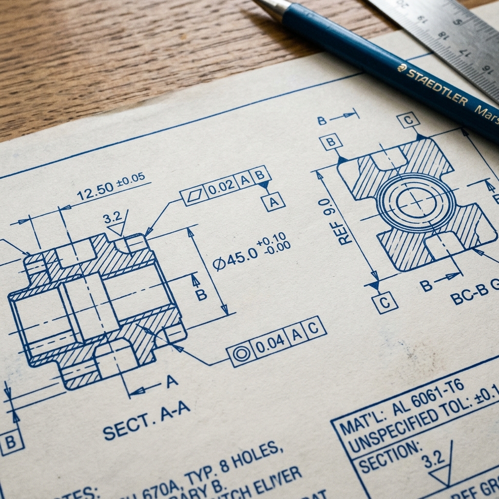
In precision engineering and manufacturing, producing parts that fit together perfectly requires clear, unambiguous communication between design engineers and machinists. Traditional linear dimensioning (using basic X and Y distances with ± tolerances) is often insufficient for complex assemblies. It can lead to 'tolerance stack-up' errors, resulting in parts that are technically within drawing limits but fail to fit together during assembly. Geometric Dimensioning & Tolerancing (GD&T) is a standardized system of symbols and rules that specifies the exact allowable variation of geometric features. At ThinkToReality, our drafting and metrology teams utilize GD&T on all 2D drawings to ensure parts are manufactured with perfect alignment and inspected with extreme accuracy.
GD&T defines the relationship between features rather than just measuring sizes. It ensures that the function of a part (how it slides, mounts, or seals) is directly controlled by the drawing tolerances. This guide outlines the core concepts of GD&T.
1. The Datum Reference Frame (DRF)
The foundation of GD&T is the Datum Reference Frame. Datums are three mutually perpendicular theoretical planes (Primary, Secondary, Tertiary) that act as the coordinate system for all geometric measurements. The physical part is held against these datum faces during machining and inspection. Establishing datums ensures that both the machinist on the shop floor and the quality inspector in the metrology lab measure the part from the exact same reference planes, eliminating measurement inconsistencies.
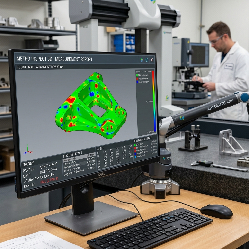
A quality control inspector using a CMM laser probe to verify geometric tolerances on a machined aluminum part.
2. Essential GD&T Symbols
GD&T uses a set of standardized symbols, displayed in feature control frames on the drawing, to specify geometric tolerances:
3. Material Condition Modifiers (MMC and LMC)
GD&T allows for the addition of modifiers like Maximum Material Condition (MMC), which represent the size limit where a part contains the most material (e.g., the smallest hole diameter or largest shaft diameter). Under MMC, if a hole is machined larger than its minimum limit, the designer gets 'bonus tolerance' on the hole location, allowing the part to pass inspection while still ensuring it will assemble cleanly, reducing scrap rates.
Conclusion: Clarity Saves Manufacturing Costs
Applying GD&T to your 2D blueprints ensures that manufacturing tolerances are directly tied to part function, eliminating misunderstandings between designers and factories. It reduces scrap, ensures first-time fitment of assemblies, and streamlines quality inspection workflows. Contact ThinkToReality's CAD drafting team to get your 2D manufacturing blueprints professionally detailed with GD&T controls today.
Related Insights
Sheet Metal Design & Precision Fabrication Guide: DFM Guidelines, Bending Tolerances & Manufacturing in India
A definitive engineering guide to precision sheet metal design and custom fabrication in India. Learn essential DFM rules, K-factor & bend deductions, CNC fiber laser cutting, press brake forming, materials, and regional manufacturing across Delhi NCR, Pune, Bengaluru & India.
Industrial 3D Printing Services in India: Technologies, Materials, Costing & Scale Production Guide
A comprehensive guide to industrial 3D printing in India. Compare FDM, SLA, SLS, and DMLS metal technologies, engineering materials, cost calculations, and batch manufacturing workflows.