
Snap-Fit Design Guide: How to Design Robust Cantilever Snaps for 3D Printed & Molded Enclosures
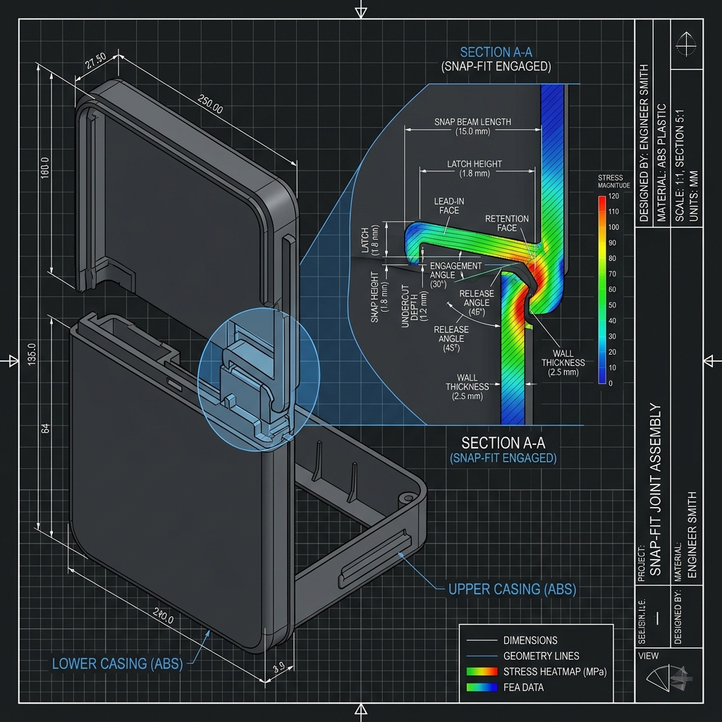
In modern product design, snap-fit joints are the most popular method for assembling plastic enclosures, sensor casings, and consumer electronics. They eliminate the need for screws, rivets, or adhesives, reducing part counts and assembly times. However, designing snap-fits requires precise calculations. If a snap-fit is too stiff, it will break during assembly; if it is too loose, the enclosure will rattle or slip open. At ThinkToReality, our industrial designers and engineers work with client CAD models daily to optimize snap-fit dimensions for both 3D printing and injection molding.
The most common snap-fit configuration is the cantilever snap-fit, consisting of a flexible beam with a hook at the end. During assembly, the beam deflects as the hook slides over a mating lip, then snaps back into a relaxed position. This guide details the engineering formulas and design tips for cantilever snaps.
1. Stress and Strain Limits
The deflection of the cantilever beam creates bending strain. To prevent permanent deformation or fracture, the strain must remain below the material's allowable limit. For ABS, the maximum strain limit is typically 5%, while for polycarbonate, it can reach up to 9%. The strain (e) is calculated using the formula: e = (3 * t * Y) / (2 * L^2), where 't' is the beam thickness, 'Y' is the deflection depth, and 'L' is the beam length. Increasing the beam length or reducing its thickness lowers the strain, preventing snap failure.
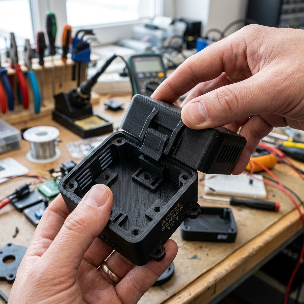
A physical 3D printed matte-black enclosure showing a cantilever snap-fit locking satisfyingly into place.
2. Adding Large Fillets at the Base
A sharp internal corner at the base of the cantilever beam creates a massive stress concentration point. Over 90% of snap-fit failures occur because of a sharp base corner. To distribute the bending stresses evenly, always add a radius (fillet) at the base of the snap. The radius should be at least 0.5 times the beam thickness to ensure robust, long-term durability.
3. The Tapered Beam Solution
A standard rectangular beam concentrates stress at its base, while the tip remains underutilized. By tapering the beam thickness from the base to the tip (e.g., making the tip half the thickness of the base), you distribute the stress evenly along the entire beam length. This reduces the strain at the base, allowing for larger deflections and higher retention forces.
4. Draft Angles and Tooling Constraints
If the part is intended for injection molding, the snap-fit hook represents an undercut. Molds require sliders or lifters to release undercuts, which increases tooling complexity and cost. Designing snap-fits that allow the mold to open without sliders (using shut-offs or holes in the casing wall directly beneath the hook) will save you lakhs in tooling costs. Always consult with ThinkToReality's DFM engineers to check tooling layouts.
Conclusion: A Balanced Joint
Mastering snap-fit joints requires balancing beam thickness, length, material elasticity, and mold constraints. By following this guide—radiusing the base corners, tapering the beam, and checking strain limits—you will ensure your enclosures assemble cleanly and hold securely. Contact ThinkToReality to verify your snap-fit designs today.
Related Insights
Sheet Metal Design & Precision Fabrication Guide: DFM Guidelines, Bending Tolerances & Manufacturing in India
A definitive engineering guide to precision sheet metal design and custom fabrication in India. Learn essential DFM rules, K-factor & bend deductions, CNC fiber laser cutting, press brake forming, materials, and regional manufacturing across Delhi NCR, Pune, Bengaluru & India.
Industrial 3D Printing Services in India: Technologies, Materials, Costing & Scale Production Guide
A comprehensive guide to industrial 3D printing in India. Compare FDM, SLA, SLS, and DMLS metal technologies, engineering materials, cost calculations, and batch manufacturing workflows.